Floating Gap

HONGSBELT modular conveyor belt is assembled by linking modules to complete the belt, and it is driven by sprockets. The teeth of sprocket will be processed into the geometric ratio angle; when the belt surface passes through the sprocket, there will be a drop between the jointing top and the belt surface, that is the floating gap. Therefore, please pay attention to the floating gap when installing the dead plate, no matter what the loading products exit or enter the belt through the dead plate. Especially for the loading of miniature products.
-
When the products are passing through the dead plate and going to get into the belt surface, the dead plate should be 0.8mm higher than the belt surface.
-
When the products are passing through the dead plate and going to get off the belt surface, the dead plate should be 0.8mm lower than the belt surface.
Floating Gap Dimensional Reference Table (G)
|
unit : mm
|
|
Series
|
Thickness of Belt
|
Sprocket Diameter (PD)
|
Number of Teeth
|
Floating Gap ( G )
|
|
100
|
16
|
133
|
8
|
5.6
|
|
164
|
10
|
4.5
|
|
196
|
12
|
4.0
|
|
260
|
16
|
3.0
|
|
200
|
10
|
64
|
8
|
2.6
|
|
98
|
12
|
1.7
|
|
163
|
20
|
1
|
|
300
|
15
|
120
|
8
|
4.3
|
|
185
|
12
|
3.3
|
|
400
|
7
|
26
|
8
|
1
|
|
38.5
|
12
|
0.3
|
|
76.5
|
24
|
0
|
|
500
|
13
|
93
|
12
|
1.3
|
|
190
|
24
|
0.5
|
Dead Plate

We recommend to adopt above 5mm thick carbon steel, stainless steel or high hardness alloy steel etc as the material for manufacturing dead plate. It is important to take account of the each gap of the transfer position, to make the loading products pass through the transfer position smoothly.
Please refer to the Basic Dimension in Design Specification chapter to get value C, and refer to the Floating Gap in this chapter to get value G, and then use the formula below, the calculation result will be the actual dimension of floating gap.
|
FORMULA :
|
E = C X 1.05
A = ( 2 X E ) ( G + G’ )
|
Design Specification of Side Transfer

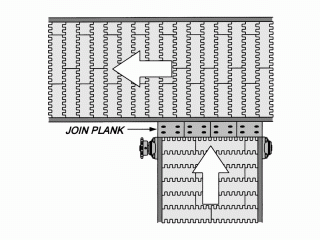
Generally, the 90 degree transfer application is in common use of the integral conveyance procedure. We recommend you to adopt HOMGSBELT turning belt; it can make you use the space flexibly.

If the factory space is not big enough for the minimum turning radius of HOMGSBELT turning belt, it is necessary to adopt side transfer design in the frame to solve this problem.
Auxiliary Rollers
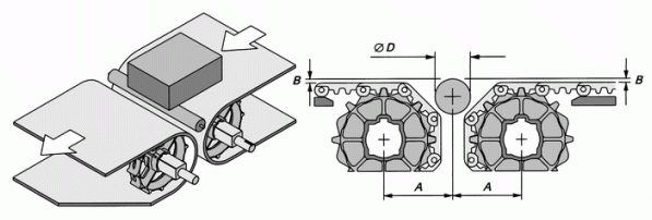
For the design of transfer position between two conveyors, if the bottom of loading products is flat and its length is over 150mm, except the dead plate, it also can make use of auxiliary transfer roller to assist conveyor belt to get the smooth and better transfer motion during operation.
Design Specification of Auxiliary Transfer Rollers in Drive / Idler Position

|
unit : mm
|
|
Series
|
Thickness (Belt)
|
Sprocket Dia.
|
Number of Teeth
|
A (min.)
|
B (min.) |
D (max.) |
|
100
|
16
|
133
|
8
|
85
|
0~1
|
34
|
|
164
|
10
|
100
|
40
|
|
196
|
12
|
116
|
50
|
|
260
|
16
|
150
|
66
|
|
200
|
10
|
64
|
8
|
47
|
20
|
|
98
|
12
|
63
|
25
|
|
163
|
20
|
95
|
40
|
|
300
|
15
|
120
|
8
|
88
|
40
|
|
185
|
12
|
106
|
44
|
|
400
|
7
|
26
|
8
|
20
|
10
|
|
38.5
|
12
|
28
|
15
|
|
76.5
|
24
|
53
|
25
|
|
500
|
13
|
93
|
12
|
64
|
25
|
|
190
|
24
|
118
|
40
|
Design Specification of Auxiliary Transfer Rollers in Platform Transfer

|
Unit : mm
|
|
Series
|
Thickness (Belt)
|
Sprocket Dia.
|
Number of Teeth
|
A (min.)
|
B (min.) |
C (min.) |
D (max.) |
|
100
|
16
|
133
|
8
|
74
|
0~1
|
23
|
20
|
|
164
|
10
|
92
|
28
|
25
|
|
196
|
12
|
106
|
33
|
30
|
|
260
|
16
|
138
|
41
|
38
|
|
200
|
10
|
64
|
8
|
42
|
18
|
15
|
|
98
|
12
|
60
|
21
|
18
|
|
163
|
20
|
93
|
28
|
25
|
|
300
|
15
|
120
|
8
|
76
|
28
|
25
|
|
185
|
12
|
108
|
30
|
27
|
|
400
|
7
|
26
|
8
|
17
|
9
|
6
|
|
38.5
|
12
|
24
|
12
|
9
|
|
76.5
|
24
|
45
|
18
|
15
|
|
500
|
13
|
93
|
12
|
56
|
18
|
15
|
|
190
|
24
|
108
|
28
|
25
|
Guide Device
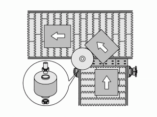
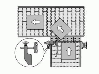
When dead plates or auxiliary transfer rollers are used for the transfer position of conveyor system, for the linear speed difference or the centrifugal force, the products will be thrown out or deviate from the center position of the belt. For the time being, it is necessary to install the guide device to assist the products pass through the turning position smoothly and within the effective transporting area.
Design Specification of Guide Roller

The guide rollers are usually made of metal material. Its guiding radius is approximately 1/4 effective width of the belt . If the loading products are demanded to enhance the friction, it should adopt the rubber or PVC material to wrap the surface of the guide rollers. It is especially suitable for the large or heavy loading of transporting products. Using ball bearings for the guide roller can make the roller rotates more smooth.
Design Specification of Guide Rail

Most of guide devices are usually made of the plastic material with lower friction, such as UHMW, HDPE and so on. It could be designed into many shapes or appearance for installation demands. Guide rails are appropriate for medium-sized or miniature loading of transporting application. The guide rails are also made of the plastic material with lower friction. The manufacturers can offer many guide rails in all kinds of shapes for customers’ demands.
When the conveyor system adopt the dead plate or auxiliary bearing from one conveyor to another at a 90 degree angle, to combine guide rollers with guide rails will make the transporting procedure more smooth and easy.
Please pay attention to if the products would hit the outside guide rail because of the centrifugal force when belt runs to the turning point, or exceed the effective range of belt carry way and result in the products piling up and jamming the production line. In general, the effective width of belt must larger than the maximum width of loading products.


